Difference between revisions of "Motor Starting Calculation"
(Created page with "== Introduction == right|thumb|300px|Figure 1. High voltage motor (courtesy of ABB) This article considers the transient effects of motor starting on...") |
|||
| Line 394: | Line 394: | ||
== Computer Software == | == Computer Software == | ||
| − | Motor starting is a standard component of most | + | Motor starting is a standard component of most Power_Systems_Analysis_Software|power systems analysis software (e.g. ETAP, PTW, PowerFactory, etc) and this calculation is really intended to be done using this software. The numerical calculation performed by the software should also solve the power flow problem through an iterative algorithm (e.g. such as Newton-Rhapson). |
== What Next? == | == What Next? == | ||
Latest revision as of 05:27, 4 May 2021
Introduction
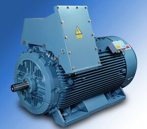
This article considers the transient effects of motor starting on the system voltage. Usually only the largest motor on a bus or system is modelled, but the calculation can in principle be used for any motor. It's important to note that motor starting is a transient power flow problem and is normally done iteratively by computer software. However a static method is shown here for first-pass estimates only.
Why do the calculation?
When a motor is started, it typically draws a current 6-7 times its full load current for a short duration (commonly called the locked rotor current). During this transient period, the source impedance is generally assumed to be fixed and therefore, a large increase in current will result in a larger voltage drop across the source impedance. This means that there can be large momentary voltage drops system-wide, from the power source (e.g. transformer or generator) through the intermediary buses, all the way to the motor terminals.
A system-wide voltage drop can have a number of adverse effects, for example:
- Equipment with minimum voltage tolerances (e.g. electronics) may malfunction or behave aberrantly
- Undervoltage protection may be tripped
- The motor itself may not start as torque is proportional to the square of the stator voltage, so a reduced voltage equals lower torque. Induction motors are typically designed to start with a terminal voltage >80%
When to do the calculation?
This calculation is more or less done to verify that the largest motor does not cause system wide problems upon starting. Therefore it should be done after preliminary system design is complete. The following prerequisite information is required:
- Key single line diagrams
- Preliminary load schedule
- Tolerable voltage drop limits during motor starting, which are typically prescribed by the client
Calculation Methodology
This calculation is based on standard impedance formulae and Ohm's law. To the author's knowledge, there are no international standards that govern voltage drop calculations during motor start.
It should be noted that the proposed method is not 100% accurate because it is a static calculation. In reality, the voltage levels are fluctuating during a transient condition, and therefore so are the load currents drawn by the standing loads. This makes it essentially a load flow problem and a more precise solution would solve the load flow problem iteratively, for example using the Newton-Rhapson or Gauss-Siedel algorithms. Notwithstanding, the proposed method is suitably accurate for a first pass solution.
The calculation has the following six general steps:
- Step 1: Construct the system model and assemble the relevant equipment parameters
- Step 2: Calculate the relevant impedances for each equipment item in the model
- Step 3: Refer all impedances to a reference voltage
- Step 4: Construct the equivalent circuit for the voltage levels of interest
- Step 5: Calculate the initial steady-state source emf before motor starting
- Step 6: Calculate the system voltages during motor start
Step 1: Construct System Model and Collect Equipment Parameters
The first step is to construct a simplified model of the system single line diagram, and then collect the relevant equipment parameters. The model of the single line diagram need only show the buses of interest in the motor starting calculation, e.g. the upstream source bus, the motor bus and possibly any intermediate or downstream buses that may be affected. All running loads are shown as lumped loads except for the motor to be started as it is assumed that the system is in a steady-state before motor start.
The relevant equipment parameters to be collected are as follows:
- Network feeders: fault capacity of the network (VA), X/R ratio of the network
- Generators: per-unit transient reactance, rated generator capacity (VA)
- Transformers: transformer impedance voltage (%), rated transformer capacity (VA), rated current (A), total copper loss (W)
- Cables: length of cable (m), resistance and reactance of cable ()
- Standing loads: rated load capacity (VA), average load power factor (pu)
- Motor: full load current (A), locked rotor current (A), rated power (W), full load power factor (pu), starting power factor (pu)
Step 2: Calculate Equipment Impedances
Using the collected parameters, each of the equipment item impedances can be calculated for later use in the motor starting calculations.
Network Feeders
Given the approximate fault level of the network feeder at the connection point (or point of common coupling), the impedance, resistance and reactance of the network feeder is calculated as follows:
Where is impedance of the network feeder ()
- is resistance of the network feeder ()
- is reactance of the network feeder ()
- is the nominal voltage at the connection point (Vac)
- is the fault level of the network feeder (VA)
- is a voltage factor which accounts for the maximum system voltage (1.05 for voltages <1kV, 1.1 for voltages >1kV)
- is X/R ratio of the network feeder (pu)
Synchronous Generators
The transient resistance and reactance of a synchronous generator can be estimated by the following:
Where is the transient reactance of the generator ()
- is the resistance of the generator ()
- is a voltage correction factor (pu)
- is the per-unit transient reactance of the generator (pu)
- is the nominal generator voltage (Vac)
- is the nominal system voltage (Vac)
- is the rated generator capacity (VA)
- is the X/R ratio, typically 20 for 100MVA, 14.29 for 100MVA, and 6.67 for all generators with nominal voltage 1kV
- is a voltage factor which accounts for the maximum system voltage (1.05 for voltages <1kV, 1.1 for voltages >1kV)
- is the power factor of the generator (pu)
Transformers
The impedance, resistance and reactance of two-winding transformers can be calculated as follows:
Where is the impedance of the transformer ()
- is the resistance of the transformer ()
- is the reactance of the transformer ()
- is the impedance voltage of the transformer (pu)
- is the rated capacity of the transformer (VA)
- is the nominal voltage of the transformer at the high or low voltage side (Vac)
- is the rated current of the transformer at the high or low voltage side (I)
- is the total copper loss in the transformer windings (W)
Cables
Cable impedances are usually quoted by manufacturers in terms of Ohms per km. These need to be converted to Ohms based on the length of the cables:
Where is the resistance of the cable {)
- is the reactance of the cable {)
- is the quoted resistance of the cable {)
- is the quoted reactance of the cable {)
- is the length of the cable {m)
Standing Loads
Standing loads are lumped loads comprising all loads that are operating on a particular bus, excluding the motor to be started. Standing loads for each bus need to be calculated.
The impedance, resistance and reactance of the standing load is calculated by:
Where is the impedance of the standing load {)
- is the resistance of the standing load {)
- is the reactance of the standing load {)
- is the standing load nominal voltage (Vac)
- is the standing load apparent power (VA)
- is the average load power factor (pu)
Motors
The motor's transient impedance, resistance and reactance is calculated as follows:
Where is transient impedance of the motor ()
- is transient resistance of the motor ()
- is transient reactance of the motor ()
- is ratio of the locked rotor to full load current
- is the motor locked rotor current (A)
- is the motor nominal voltage (Vac)
- is the motor rated power (W)
- is the motor full load power factor (pu)
- is the motor starting power factor (pu)
Step 3: Referring Impedances
Where there are multiple voltage levels, the equipment impedances calculated earlier need to be converted to a reference voltage (typically the HV side) in order for them to be used in a single equivalent circuit.
The winding ratio of a transformer can be calculated as follows:
Where is the transformer winding ratio
- is the transformer nominal secondary voltage at the principal tap (Vac)
- is the transformer nominal primary voltage (Vac)
- is the specified tap setting (%)
Using the winding ratio, impedances (as well as resistances and reactances) can be referred to the primary (HV) side of the transformer by the following relation:
Where is the impedance referred to the primary (HV) side ()
- is the impedance at the secondary (LV) side ()
- is the transformer winding ratio (pu)
Conversely, by re-arranging the equation above, impedances can be referred to the LV side:
Step 4: Construct the Equivalent Circuit
The equivalent circuit essentially consists of a voltage source (from a network feeder or generator) plus a set of complex impedances representing the power system equipment and load impedances.
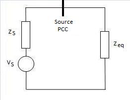
The next step is to simplify the circuit into a form that is nearly the Thévenin equivalent circuit, with a circuit containing only a voltage source (), source impedance () and equivalent load impedance ().
This can be done using the standard formulae for series and parallel impedances, keeping in mind that the rules of complex arithmetic must be used throughout. This simplification to a "Near" Thévenin equivalent circuit should be done both with the motor off (open circuit) and the motor in a starting condition.
Step 5: Calculate the Initial Source EMF
Assuming that the system is initially in a steady-state condition, we need to first calculate the initial emf produced by the power source (i.e. feeder connection point or generator terminals). This voltage will be used in the transient calculations (Step 6) as the initial source voltage.
Assumptions regarding the steady-state condition:
- The source point of common coupling (PCC) is at its nominal voltage
- The motor is switched off
- All standing loads are operating at the capacity calculated in Step 2
- All transformer taps are set at those specified in Step 2
- The system is at a steady-state, i.e. there is no switching taking place throughout the system
Since we assume that there is nominal voltage at the PCC, the initial source emf can be calculated by voltage divider:
Where is the initial emf of the power source (Vac)
- is the nominal voltage (Vac)
- is the source impedance ()
- is the equivalent load impedance with the motor switched off ()
Step 6: Calculate System Voltages During Motor Start
It is assumed in this calculation that during motor starting, the initial source emf calculated in Step 5 remains constant; that is, the power source does not react during the transient period. This is a simplifying assumption in order to avoid having to model the transient behaviour of the power source.
Next, we need to calculate the overall system current that is supplied by the power source during the motor starting period. To do this, we use the "Near" Thevenin equivalent circuit derived earlier, but now include the motor starting impedance. A new equivalent load impedance during motor starting will be calculated.
The current supplied by the power source is therefore:
Where is the system current supplied by the source (A)
- is the initial source emf (Vac)
- is the equivalent load impedance during motor start ()
- is the source impedance ()
The voltage at the source point of common coupling (PCC) is:
Where is the voltage at the point of common coupling (Vac)
- is the initial source emf (Vac)
- is the system current supplied by the source (A)
- is the source impedance ()
The downstream voltages can now be calculated by voltage division and simple application of Ohm's law. Specifically, we'd like to know the voltage at the motor terminals and any buses of interest that could be affected. Ensure that the voltages are acceptably within the prescribed limits, otherwise further action needs to be taken (refer to the What's Next? section).
Worked Example
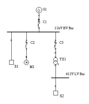
The worked example here is a very simple power system with two voltage levels and supplied by a single generator. While unrealistic, it does manage to demonstrate the key concepts pertaining to motor starting calculations.
Step 1: Construct System Model and Collect Equipment Parameters
The power system has two voltage levels, 11kV and 415V, and is fed via a single 4MVA generator (G1). The 11kV bus has a standing load of 950kVA (S1) and we want to model the effects of starting a 250kW motor (M1). There is a standing load of 600kVA at 415V (S2), supplied by a 1.6MVA transformer (TX1). The equipment and cable parameters are as follows:
| Equipment | Parameters |
|---|---|
| Generator G1 |
|
| Generator Cable C1 |
(R = 0.0522 \km, X = 0.0826 \km) |
| 11kV Standing Load S1 |
|
| Motor M1 |
|
| Motor Cable C2 |
(R = 0.668 \km, X = 0.115 \km) |
| Transformer TX1 |
|
| Transformer Cable C3 |
(R = 0.196 \km, X = 0.096 \km) |
| 415V Standing Load S2 |
|
Step 2: Calculate Equipment Impedances
Using the patameters above and the equations outlined earlier in the methodology, the following impedances were calculated:
| Equipment | Resistance () | Reactance () |
|---|---|---|
| Generator G1 | 0.65462 | 9.35457 |
| Generator Cable C1 | 0.00261 | 0.00413 |
| 11kV Standing Load S1 | 106.98947 | 69.10837 |
| Motor M1 | 16.77752 | 61.02812 |
| Motor Cable C2 | 0.1002 | 0.01725 |
| Transformer TX1 (Primary Side) | 0.60027 | 4.49762 |
| Transformer Cable C3 | 0.01176 | 0.00576 |
| 415V Standing Load S2 | 0.22963 | 0.17223 |
Step 3: Referring Impedances
11kV will be used as the reference voltage. The only impedance that needs to be referred to this reference voltage is the 415V Standing Load (S2). Knowing that the transformer is set at principal tap, we can calculate the winding ratio and apply it to refer the 415V Standing Load impedance to the 11kV side:
The resistance and reactance of the standing load referred to the 11kV side is now, R = 161.33333 and X = 121.00 .
Step 4: Construct the Equivalent Circuit
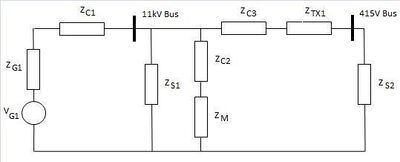
The equivalent circuit for the system is shown in the figure to the right. The "Near" Thevenin equivalent circuit is also shown, and we now calculate the equivalent load impedance in the steady-state condition (i.e. without the motor and motor cable impedances included):
Similarly the equivalent load impedance during motor starting (with the motor impedances included) can be calculated as as follows:
Step 5: Calculate the Initial Source EMF
Assuming that there is nominal voltage at the 11kV bus in the steady-state condition, the initial generator emf can be calculated by voltage divider:
-
- Vac
Step 6: Calculate System Voltages During Motor Start
Now we can calculate the transient effects of motor starting on the system voltages. Firstly, the current supplied by the generator during motor start is calculated:
Next, the voltage at the 11kV bus can be found:
-
- Vac (or 87.98% of nominal voltage)
The voltage at the motor terminals can then be found by voltage divider:
-
- Vac (or 87.92% of nominal voltage)
The voltage at the low voltage bus is:
-
- Vac, then referred to the LV side = 359.39Vac (or 86.60% of nominal voltage)
Any other voltages of interest on the system can be determined using the same methods as above.
Suppose that our maximum voltage drop at the motor terminals is 15%. From above, we have found that the voltage drop is 12.08% at the motor terminals. This is a slightly marginal result and it may be prudent to simulate the system in a software package to confirm the results.
Computer Software
Motor starting is a standard component of most Power_Systems_Analysis_Software|power systems analysis software (e.g. ETAP, PTW, PowerFactory, etc) and this calculation is really intended to be done using this software. The numerical calculation performed by the software should also solve the power flow problem through an iterative algorithm (e.g. such as Newton-Rhapson).
What Next?
If the results of the calculation confirm that starting the largest motor does not cause any unacceptable voltage levels within the system, then that's the end of it (or perhaps it could be simulated in a power systems analysis software package to be doubly sure!). Otherwise, the issue needs to be addressed, for example by:
- Reduce the motor starting current, e.g. via soft-starters, star-delta starters, etc
- Reduce the source impedances, e.g. increase the size of the generator, transformer, supply cables, etc
The calculation should be performed iteratively until the results are acceptable.


![{\displaystyle Z_{eq}=Z_{C1}+\left[Z_{S1}||\left(Z_{C3}+Z_{TX1}+Z_{S2}\right)\right]\,}](https://wikimedia.org/api/rest_v1/media/math/render/svg/0c94157107f069f03ad808fd53e667022ab1b900)

![{\displaystyle Z_{eq,s}=Z_{C1}+\left[Z_{S1}||\left(Z_{C3}+Z_{TX1}+Z_{S2}\right)||Z_{C2}+Z_{M1}\right]\,}](https://wikimedia.org/api/rest_v1/media/math/render/svg/f2720ed1f9aab37b2c0e01a931108f57dfe7c7d3)


