Resonance
Classical Derivations
Series Resonance
The classical circuit to demonstrate series resonance is the RLC circuit shown in the figure right, which shows a voltage source connected to R, L and C impedances in series. Given a fixed ac voltage source U operating at angular frequency , the current in the circuit is given by the following:
The current is at a maximum when the impedance is at a minimum. So given constant R, L and C, the minimum impedance occurs when:
or
This angular frequency is called the resonant frequency of the circuit. At this frequency, the current in the series circuit is at a maximum and this is referred to as a point of series resonance. The significance of this in practice is when harmonic voltages at the resonant frequency cause high levels of current distortion.
Parallel Resonance
The classical circuit to demonstrate series resonance is the RLC circuit shown in the figure right, which shows a current source connected to R, L and C impedances in parallel. Given a fixed ac current source I operating at angular frequency , the voltage across the impedances is given by the following:
The voltage is at a maximum when the impedance is also at a maximum. So given constant R, L and C, the maximum impedance occurs when:
or
Notice that the resonant frequency is the same as that in the series resonance case. At this resonant frequency, the voltage in the parallel circuit is at a maximum and this is referred to as a point of parallel resonance. The significance of this in practice is when harmonic currents at the resonant frequency cause high levels of voltage distortion.
Resonance in Practical Circuits
Series Resonance
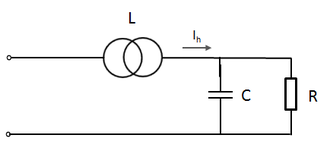
Here a distorted voltage at the input of the transformer can cause high harmonic current distortion () at the resonant frequency of the RLC circuit.
Parallel Resonance
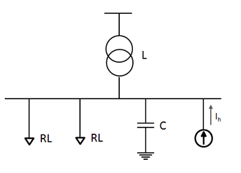
In this more common scenario, a harmonic current source () can cause high harmonic voltage distortion on the busbar at the resonant frequency of the RLC circuit. The harmonic current source could be any non-linear load, e.g. power electronics interfaces such as converters, switch-mode power supplies, etc.


