Short Circuit
A short circuit is an electrical fault where a conductive path (usually of low impedance) is formed between two or more conductive parts of an electrical system (e.g. phase-phase, phase-earth, phase-neutral, etc). This article looks at the nature of short circuits and tries to break down and explain the constituent parts of fault currents. Note that the terms "short circuit" and "fault" are often used interchangeably.
In most networks, a short circuit is similar to the closing transient of an RL circuit, where the R and L components are the impedances of the source(s). The transient characteristics of short circuit currents vary depending on whether they are near or far from synchronous generators. The sections below describe the two general types of short circuits:
Near-to-Generator Short Circuit
A fault close to a synchronous generator has the following maximum short circuit current :
Where is the phase-to-neutral rms voltage at the generator terminals (V)
- is the generator direct-axis subtransient reactance ()
- is the generator direct-axis transient reactance ()
- is the generator synchronous reactance ()
- is the generator subtransient time constant (s)
- is the generator transient time constant (s)
- is the aperiodic time constant (s)
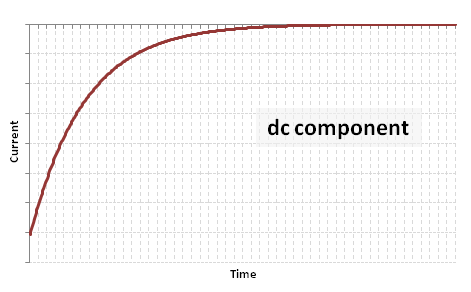
From the above equation, it can be seen that the short circuit current can be broken up into an aperiodic current (dc component of the short circuit):
And a series of three damped sinusoidal waveforms corresponding to the following distinct stages:
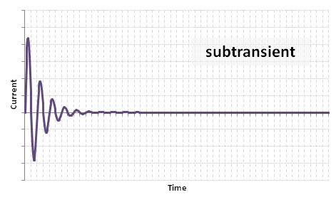
(1) Subtransient component:
This period typically lasts 10 to 20ms from the start of the fault. The subtransient reactance is due to the flux casued by the stator currents crossing the air gap and reaching the rotor surface or amortisseur / damper windings.
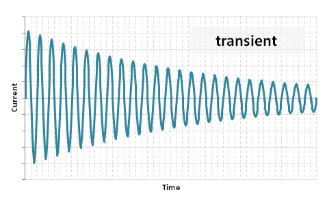
(2) Transient component:
This period typically lasts 100 to 400ms after the subtransient period. The transient reactance occurs when all the damping currents in the rotor surface or amortisseur / damper windings have decayed, but while the damping currents in the field winding are still in action.
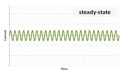
(3) Steady-state component:
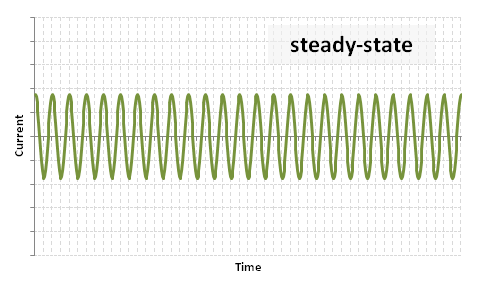
The steady-state occurs after the transient period when all the damping currents in the field windings have decayed, and essentially remains until the fault is cleared.
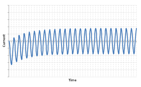
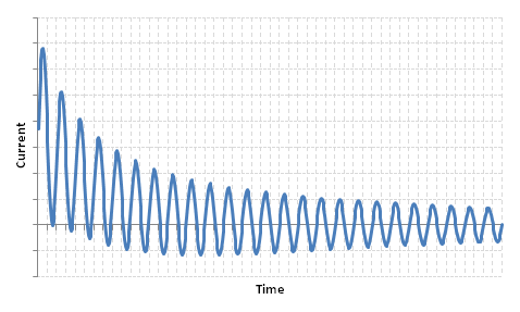
Putting these all together, we get the familiar near-to-generator short circuit waveform:
Far-from-Generator Short Circuit
In short circuits occurring far from synchronous generators, we can ignore the effects of the generator subtransient behaviour. It can be shown through transient circuit analysis that the maximum far-from-generator short circuit is as follows:
Where is the rms voltage of the circuit (V)
- is the fault impedance ()
- is the R/X ratio at the point of fault (pu)
- is a phase angle comprising the angle at the time of fault and the steady-state power angle (rad)
We can see that there are two components:
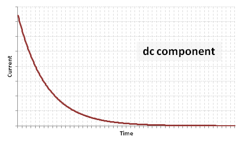
(1) A decaying aperiodic component:
(note here that the arbitrary phase angle yields a negative magnitude)
(2) A steady state component:
Putting these together, we get the total far-from-generator fault current:
During the transient period, the peak transient current is typically 1.5 to 2.5 times higher than the peak steady state current.

![{\displaystyle i_{sc}(t)=E{\sqrt {2}}\left[\left({\frac {1}{X_{d}''}}-{\frac {1}{X_{d}'}}\right)e^{-t/t_{d}''}+\left({\frac {1}{X_{d}'}}-{\frac {1}{X_{d}}}\right)e^{-t/t_{d}'}+{\frac {1}{X_{d}}}\right]\sin(\omega t)+{\frac {E{\sqrt {2}}}{X_{d}''}}e^{-t/t_{a}}\,}](https://wikimedia.org/api/rest_v1/media/math/render/svg/8de4beceba71dfebc403b458538a020745f43839)





![{\displaystyle i_{sc}(t)={\frac {E{\sqrt {2}}}{Z_{sc}}}\left[\sin \left(\omega t+\phi \right)-\sin(\phi )e^{-{\frac {R}{X}}\omega t}\right]\,}](https://wikimedia.org/api/rest_v1/media/math/render/svg/299f2823b082d8b21b32e943bb16d90c16b48be5)


