Symmetrical Components
Symmetrical components is a mathematical method for representing an unbalanced set of phasors into three decoupled (independent) sets of phasors - two balanced sets and a third set with identical phasors. The method was originally developed in 1918 by Charles LeGeyt Fortescue and simplifies the analysis of unbalanced polyphase systems (e.g. commonly used for three-phase voltage, current and impedance phasors).
Basic Transformation
An arbitrary set of n phasors has 2n degrees of freedom, i.e. for each phasor, there is a magnitude and independent phase angle. Fortescue proposed a transformation that would also have 2n degrees of freedom, but have the advantage of symmetry.
We will restrict ourselves to sets of 3 phasors, which is the most useful for modern electrical engineering. Given a set of three arbitrary phasors, say voltage phasors, we can express these as follows:
Where , and are the set of arbitrary voltage phasors (balanced or otherwise)
- , and are the set of zero sequence voltage phasors
- , and are the set of positive sequence voltage phasors
- , and are the set of negative sequence voltage phasors
We have essentially broken down each original phasor into a linear combination of three phasors. But wait, aren't we now making this more complicated? If we left it as is, then that would certainly be true. After all, we initially had 6 degrees of freedom (i.e. 2 for each of the three phasors) and now we have 18.
But we let's impose some constraints on the new sets of phasors:
- Firstly, let's say that the positive sequence phasors are balanced and perfecty symmetrical. This means that we can describe the set of three phasors using only a single reference phasor (an arbitrary choice, but we'll choose phasor a). Therefore:
- where is the 120o rotation operator ()
- Secondly, we impose a similar constraint on the negative sequence phasors. They must be balanced and perfectly symmetrical, but they have the oppositve phase sequence to the positive sequence phasors, i.e. the peaks of the phasors occur in the opposite order (acb instead of abc). Mathematically,
- Lastly for the zero sequence phasors, we impose the constraint that they shall all be identical, i.e:
Each of these three constraints removes 4 degrees of freedom and in the end, we can describe everything with just 3 phasors and 6 degrees of freedom (the same as the initial set of phasors). However, we have the advantage that the new phasors are balanced and symmetrical (or are identical in the case of the zero sequence phasors).
In matrix notation, we can write the set of equations as follows:
Where , and are the set of arbitrary voltage phasors (balanced or otherwise)
- is the zero-sequence voltage component
- is the positive-sequence voltage component
- is the negative-sequence voltage component
- is the 120o rotation operator ()
The inverse of the above gives the transformation equation:
Visual Depiction
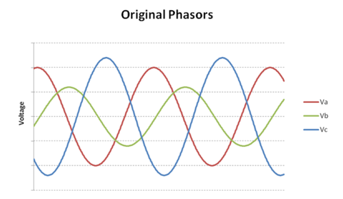
Suppose we had a set of three unbalanced voltage waveforms as follows:
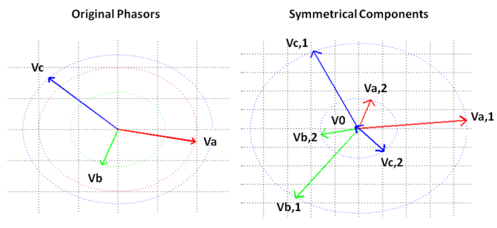
The phasor plot of the original phasors and the symmetrical component decomposition is shown below:
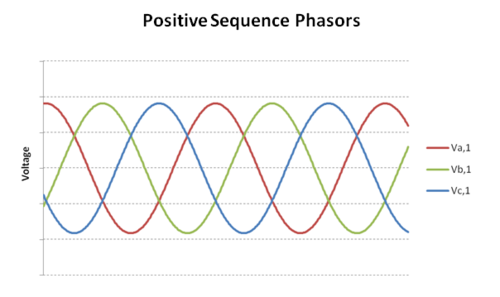
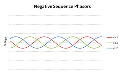
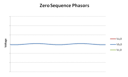
The time-domain waveforms of the positive, negative and zero sequence phasors is shown below:
The time-domain plots above nicely illustrate the difference between positive and negative sequences. Look at the positive and negative sequence plots. In the positive sequence plot, the waveform peaks appear in the following order: Va (red), Vb (blue), Vc (green). In the negative sequence plot, the peaks are in a different order: Va (red), Vc (green), Vb (blue).
Steven Blair at the University of Strathclyde has a good interactive tool for visualising symmetrical components.
Shorthand Notation
To reduce the amount of writing, it may be preferable to refer to the original unbalanced phasors and their symmetrical components via the following shorthand notation.
The original unbalanced phasors are denoted :
The transformed symmetrical component phasors are denoted :
The transformation matrices are denoted:
Therefore in matrix form, the symmetrical component transformations are as follows:
Voltage, Current and Impedances
The transformation of an unbalanced three-phase network into its symmetrical components have the following relationships regarding voltage, current and impedance.
Voltage and Current
Voltage and current phasors are resolved into symmetrical components by the basic transform described above, i.e.
Impedance
Impedance is not resolved into symmetrical components in such a straightforward manner since voltage, current and impedance are related by Ohm's law. Therefore, we want an expression for the symmetrical components of impedance such that Ohm's law is satisfied:
To do this, we work backward from the original unbalanced phasors, and then apply the transforms:
This is now in the form as the first equation above and therefore we can conclude that:
Note that the impedance is a symmetric 3 x 3 matrix that consists of self-impedances on the diagonal and mutual impedances (between phases) on the off-diagonals:
Restating Ohnm's law in terms of symmetrical components, we get:
From the equation above, we can see that there is cross-coupling between the symmetrical components of the network quantities. For example, the zero sequence voltage is equal to the weighted sum of the positive, negative and zero sequence currents:
Balanced Impedances
A special case occurs in systems with balanced impedances, i.e. where the impedance matrices are of the form:
In such balanced systems, the transformed impedance matrix is a diagonal matrix of the form:
Because all of the off-diagonals are zero, the corresponding positive, negative and zero sequence voltages and currents are independent from each other, i.e. they are completely de-coupled and have no cross-terms, and therefore can be treated as three de-coupled equations:
In summary, we can say that in a balanced system, the symmetrical components of netwrok quantities form a de-coupled system of equations. The de-coupled system of equations are then typically used to form sequence networks.
This result forms the basis of most analyses that use symmetrical components. For example, in unbalanced fault analysis, we first assume that the system is balanced before the fault. By doing this, we can construct the sequence networks as completely de-coupled systems. The unbalance is introduced at the fault location (e.g. a phase-to-earth fault) and the previously de-coupled sequence networks are connected together to yield the unbalanced system.
References
- [1] Charles L. Fortescue, "Method of Symmetrical Co-Ordinates Applied to the Solution of Polyphase Networks". Presented at the 34th annual convention of the AIEE (American Institute of Electrical Engineers) in Atlantic City, N.J. on 28 July 1918.
![{\displaystyle \left[{\begin{matrix}V_{a}\\V_{b}\\V_{c}\end{matrix}}\right]=\left[{\begin{matrix}V_{a,0}\\V_{b,0}\\V_{c,0}\end{matrix}}\right]+\left[{\begin{matrix}V_{a,1}\\V_{b,1}\\V_{c,1}\end{matrix}}\right]+\left[{\begin{matrix}V_{a,2}\\V_{b,2}\\V_{c,2}\end{matrix}}\right]\,}](https://wikimedia.org/api/rest_v1/media/math/render/svg/bf96ba78b1406df046678009cdd9df7b705bde1c)


![{\displaystyle \left[{\begin{matrix}V_{a}\\V_{b}\\V_{c}\end{matrix}}\right]=\left[{\begin{matrix}1&1&1\\1&a^{2}&a\\1&a&a^{2}\end{matrix}}\right]\left[{\begin{matrix}V_{0}\\V_{1}\\V_{2}\end{matrix}}\right]\,}](https://wikimedia.org/api/rest_v1/media/math/render/svg/988aa5d5bea77c9fec653bdf7d9d299f626a19ab)


![{\displaystyle \left[{\begin{matrix}V_{0}\\V_{1}\\V_{2}\end{matrix}}\right]={\frac {1}{3}}\left[{\begin{matrix}1&1&1\\1&a&a^{2}\\1&a^{2}&a\end{matrix}}\right]\left[{\begin{matrix}V_{a}\\V_{b}\\V_{c}\end{matrix}}\right]\,}](https://wikimedia.org/api/rest_v1/media/math/render/svg/3c98ac8bdac4e6949f85040fed267f4e90958898)

![{\displaystyle V_{abc}=\left[{\begin{matrix}V_{a}\\V_{b}\\V_{c}\end{matrix}}\right]\,}](https://wikimedia.org/api/rest_v1/media/math/render/svg/7474620d194feca883a450c120888afbf3d3f2d2)

![{\displaystyle V_{012}=\left[{\begin{matrix}V_{0}\\V_{1}\\V_{2}\end{matrix}}\right]\,}](https://wikimedia.org/api/rest_v1/media/math/render/svg/15c5465a0624125e660ac8a4fb2b9a2468230969)
![{\displaystyle A=\left[{\begin{matrix}1&1&1\\1&a^{2}&a\\1&a&a^{2}\end{matrix}}\right]\,}](https://wikimedia.org/api/rest_v1/media/math/render/svg/2aa365079dafd91ff2b02bc93eefe443f08c01bf)
![{\displaystyle A^{-1}=\left[{\begin{matrix}1&1&1\\1&a&a^{2}\\1&a^{2}&a\end{matrix}}\right]\,}](https://wikimedia.org/api/rest_v1/media/math/render/svg/6fa78f5e3081faa2c9376e9cc0b90f35ab67a841)


![{\displaystyle Z_{abc}=\left[{\begin{matrix}Z_{aa}&Z_{ab}&Z_{ac}\\Z_{ba}&Z_{bb}&Z_{bc}\\Z_{ca}&Z_{cb}&Z_{cc}\end{matrix}}\right]\,}](https://wikimedia.org/api/rest_v1/media/math/render/svg/3dee05a1264fa743dc688731ba20cf2fa7e26bff)
![{\displaystyle \left[{\begin{matrix}V_{0}\\V_{1}\\V_{2}\end{matrix}}\right]=\left[{\begin{matrix}Z_{00}&Z_{01}&Z_{02}\\Z_{10}&Z_{11}&Z_{12}\\Z_{20}&Z_{21}&Z_{22}\end{matrix}}\right]\left[{\begin{matrix}I_{0}\\I_{1}\\I_{2}\end{matrix}}\right]\,}](https://wikimedia.org/api/rest_v1/media/math/render/svg/eb78224fd0fffc0c8c6ded4fe1ce875f09103d22)

![{\displaystyle Z_{abc}=\left[{\begin{matrix}Z&M&M\\M&Z&M\\M&M&Z\end{matrix}}\right]\,}](https://wikimedia.org/api/rest_v1/media/math/render/svg/a34b0a3ea49b3f7ad3b2d7484d55c01ca9f232ab)

![{\displaystyle Z_{012}=\left[{\begin{matrix}Z_{0}&0&0\\0&Z_{1}&0\\0&0&Z_{2}\end{matrix}}\right]\,}](https://wikimedia.org/api/rest_v1/media/math/render/svg/ed0c132fd950b9b957a999ca33a6fb85cce8dda4)
![{\displaystyle \left[{\begin{matrix}V_{0}\\V_{1}\\V_{2}\end{matrix}}\right]=\left[{\begin{matrix}Z_{0}&0&0\\0&Z_{1}&0\\0&0&Z_{2}\end{matrix}}\right]\left[{\begin{matrix}I_{0}\\I_{1}\\I_{2}\end{matrix}}\right]\,}](https://wikimedia.org/api/rest_v1/media/math/render/svg/c987c7299ed9151acd1e6671bc9f355414d32be6)
![{\displaystyle =\left[{\begin{matrix}Z_{0}I_{0}\\Z_{1}I_{1}\\Z_{2}I_{2}\end{matrix}}\right]\,}](https://wikimedia.org/api/rest_v1/media/math/render/svg/2dcbd1626967c8bf7d2af944871b2318d8c8088b)