Difference between revisions of "Power Flow"
(Created page with "== Introduction == The objective of the '''power flow''' (or '''load flow''') calculation is to determine the steady-state operating conditions of an electrical network. The...") |
|||
| Line 130: | Line 130: | ||
== Calculated Bus Power Injections == | == Calculated Bus Power Injections == | ||
| − | The power flow problem is most commonly formulated using power injections rather than current injections. [[ | + | The power flow problem is most commonly formulated using power injections rather than current injections. [[Electrical_Power#Complex_Power_from_Phasors|Complex power]] injections at bus k can be calculated from current injections as follows: |
: <math>\boldsymbol{S}_{k} = P + jQ = \boldsymbol{V}_{k} \boldsymbol{I}^{*}_{k} </math> ... Equ. (2) | : <math>\boldsymbol{S}_{k} = P + jQ = \boldsymbol{V}_{k} \boldsymbol{I}^{*}_{k} </math> ... Equ. (2) | ||
Latest revision as of 14:02, 18 November 2020
Introduction
The objective of the power flow (or load flow) calculation is to determine the steady-state operating conditions of an electrical network. The power flow problem is formulated such that at each bus in the network, the following four variables are solved so as to fully define the power flows in the network:
- Bus voltage magnitude,
- Bus voltage angle,
- Active power injected into (or consumed at) the bus,
- Reactive power injected into (or consumed at) the bus,
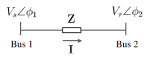
In the simplest case of AC power transmission between two buses connected by a line (as shown in Figure 1), the complex AC power flow at the receiving end bus can be calculated as follows:
Similarly, the power flow at the sending end bus is:
where is the voltage and phase angle at the sending end
- is the voltage and phase angle at the receiving end
- is the complex impedance of the line.
- is the current phasor
In power flow calculations, it is generally more convenient to represent impedances as admittances, i.e. so that the current phasors are calculated by multiplication rather than complex division:
The equations for the two bus system above form the basis of the power flow calculations. In this article, these equations are extended to larger systems of arbitrary size and topology.
Historical Context
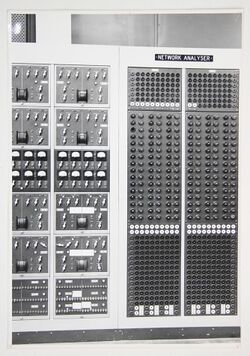
Power flow calculations evolved from the planning departments of electricity utilities in the early 20th century, where they were (and still are) used to simulate the effects of network augmentations, different load scenarios, network configurations, etc. Early power flows were solved by AC network analyzers (or calculating boards), which were analog computers containing resistors, inductors and capacitors calibrated to be a miniature scale equivalent of the actual electrical network. For large systems, these network analysers took up the space of entire rooms. As they were physical in nature, the network analysers needed to be re-wired for each different configuration, augmentation or scenario to be studied.
Starting with the seminal paper by Ward and Hale in 1956 [1], the use of digital computers would enable power flow calculations to be performed faster and in a more flexible manner. The iterative method proposed by Ward and Hale (which became known as the Gauss-Seidel method) was straightforward to implement, but exhibited poor convergence characteristics.
In 1961, Van Ness and Griffin [2] introduced Newton's method for solving power flows (which later became known as the Newton-Raphson method), which had more favourable characteristics but was limited to smaller networks due to computer memory requirements. In their 1967 paper, Tinney and Hart [3] exploited the sparsity properties of the Ybus matrix (and by extension, the Jacobian matrix) and in conjunction with numerical techniques such as triangular factorisation and optimal ordering, were able to make the Newton-Raphson algorithm practical for solving large networks using the computing resources available at the time.
In 1974, Stott and Alsac [4] recognised that in many practical networks there was decoupling between 1) active power and voltage and 2) reactive power and phase angle. The proposed an algorithm (the fast decoupled load flow) that significantly reduced the computational requirements to construct the Jacobian matrix and therefore led to large gains in computational speed (although at the expense of a little accuracy).
Per Unit Representation
To simplify the calculation of admittances / impedances across different voltage levels, it is convenient to use a per-unit representation of the network. By default, most power flow programs use a system-wide MVA base of 100MVA.
Single Phase Representation
In the basic power flow formulation, three-phase systems are represented in single-phase form, based on the assumption that the system is perfectly balanced (e.g. loads and generation are balanced, transmission lines are fully transposed, etc). This assumption holds relatively well for high voltage transmission systems, but begins to break down at smaller scales (e.g. low voltage distribution level), where a full three-phase power flow formulation is necessary.
Using a single-phase representation is convenient as it allows impedances to be formulated as single complex quantities (R + jX) rather than a 3x3 matrix of mutually coupled impedances in a full three-phase representation. Voltages in the single-phase formulation are usually referenced to earth.
Nodal Representation
The electrical network needs to be represented in such a way so that the quantities of interest (e.g. voltage, power flows, etc) can be solved using either nodal analysis or mesh analysis approaches. The nodal method is the standard approach for power flow calculations for several reasons: 1) busbars in the system can be easily translated into nodes, 2) the admittance matrix (without mutual couplings) can be built from inspection, and 3) the nodal method can exploit the sparsity of the admittance matrix.
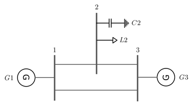
For example, consider the simple system below consisting of three buses (numbered 1, 2 and 3), two generators (G1 and G2), a load (L2) and a shunt capacitor (C2) connected via transmission lines:
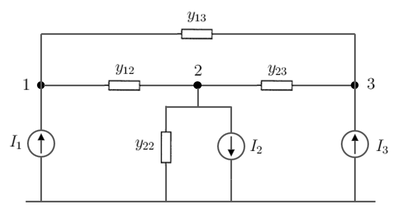
In the nodal representation, the buses are represented as nodes, the generators and load are represented as current injections while the shunt capacitor and lines are represented as admittances:
Note that the line at the bottom represents the reference node, usually taken to be an earth reference. All node voltages are expressed with respect to this reference node.
From Kirchhoff's current law, we can see that the injected currents must equal the sum of the branch currents leaving the node. For example, at node 1:
Similarly, at node 2:
Note the negative sign for the current indicating that it is a load and current is leaving the bus as opposed to being injected. Note also the effect of the shunt capacitor, which appears as a self-admittance ().
The general formulation for the current injection at node k of an n-node system is:
-
- ... Equ. (1)
Bus Admittance Matrix
We saw in Equation 1 above an expression for the current injection at an arbitrary bus in terms of admittances and bus voltages. The current injections for every bus in the network can be calculated using this equation and can be expressed in matrix form as follows:
Or in compact form:
where is the vector of bus current injections (positive values are injections, negative values are consumptions)
- is the vector of bus voltage phasors
- is the bus admittance matrix (more on this below)
The bus admittance (or Ybus) matrix is one of the fundamental building blocks of power system simulations, describing both the topology and admittances / impedances of an electrical network. The diagonal elements of the Ybus matrix are referred to as self-admittances and the off-diagonal elements are mutual admittances.
The Ybus matrix can be constructed from inspection when there are no mutual couplings between branches. The procedure for building the Ybus matrix from inspection follows on readily from Equation 1:
- 1. Self-admittances (diagonal elements): at bus k are the sum of all branch admittances connected to the bus (including shunt admittances to earth):
- 2. Mutual admittances (off-diagonal elements): between buses k and i are the negative sum of branch admittances connected between buses k and i:
The Ybus matrix is our three bus example above is:
The Ybus matrix is a square and symmetric matrix with complex values. Normally, it is also very sparse since most practical networks are not densely interconnected and thus have few non-zero branch admittance values.
Note that the Ybus matrix is non-singular only if there are shunt admittances connected (e.g. the shunt capacitor in our three-bus example above). This is easily proved by noticing that without shunt admittances, each row and column of the Ybus matrix sums to zero (i.e. it is a zero-sum matrix) and therefore does not have full rank and is not invertible.
Calculated Bus Power Injections
The power flow problem is most commonly formulated using power injections rather than current injections. Complex power injections at bus k can be calculated from current injections as follows:
- ... Equ. (2)
Given the voltages on each bus and the Ybus matrix , the bus power injections (i.e. net active and reactive power flows for the kth bus) can be calculated in rectangular coordinates as follows:
- ... Equ. (3)
- ... Equ. (4)
Where are the elements of the Ybus matrix
Classical Formulation of the Power Flow Problem
It was noted earlier that at each bus, four variables (, , and ) are required to be known to fully define the power flows in the system. To solve the power flow problem, two of the four variables need to be specified (i.e. known) a priori for each bus and the power flow calculation solves for the other two. Typically, power injections at the buses are known (e.g. measured or estimated loads or dispatched generation at the bus) and are therefore normally specified. As a result, the bus voltages and angles are generally the unknown variables to be solved.
Therefore in the classical formulation, the power flow problem is constructed as a set of non-linear algebraic power equations for the unknown variables in the system (bus voltage magnitudes and angles). The aim of the power flow calculation is to arrive at values for bus voltages and angles such that the the mismatch error between the specified and calculated power injections at each bus are within a pre-specified error tolerance.
Types of Buses
As discussed earlier, two variables of the four bus variables need to be specified at each bus. The two specified variables do not have to be the same for every bus, which leads to the definition of the following common bus types:
- (1) Swing (or slack) bus [SW]: since network losses are not known a priori, a swing bus is required where the voltage is specified, but the active power injected into the bus is unknown. The swing bus is usually designated as the voltage reference for the system. In practice, the swing bus would be analogous to a large generator responsible for load-frequency control or the point of common coupling to a larger external grid. Specified variables: ,
- (2) Voltage controlled bus [PV]: in the PV bus, the active power injected into the bus is specified along with the voltage magnitude. PV buses are typically used to represent generators where the active power injected is the generator dispatch power and an automatic voltage regulator controls the bus voltage magnitude to a specified value. PV buses can also be used for reactive power support devices which control the bus voltage to a specified value e.g. SVCs, synchronous condensers, STATCOMs, etc (in such cases, the P active power injected is zero). Specified variables: ,
- (3) Constant power bus [PQ]: in the PQ bus, the active and reactive power injected into (or consumed at) the bus is specified. PQ buses are typically used to represent constant power loads (e.g. residential, industrial, etc), where it is assumed that the active and reactive power injections are not affected by small variations in bus voltages (at steady state). Specified variables: ,
Power Mismatch Vector
The power mismatch vector is defined as a vector of the differences between the specified and calculated power injections at each bus. The power mismatch at bus k in complex form is calculated as follows:
where is the specified complex power injection at bus k
- is the calculated complex power injection at bus k (i.e. from Equation 2)
The power mismatches can also be expressed in rectangular form where the calculated active and reactive power injections are computed using Equations 3 and 4 respectively, i.e.
General Solution Procedure
- 1. Formulate the network Ybus matrix
- 2. Select a swing bus for the network
- 3. For all other buses, define the bus type (e.g. PQ or PV) and specify the known variables
- 4. Select initial voltages and angles for all buses. Commonly, a flat start is used where all voltages are initialised at pu. Alternatively, a previously calculated power flow solution ("solved case") can be used.
- 5. Calculate the power mismatch vector by using the initial voltages in Step 4 and the specified power injections in Step 3.
- 6. Apply an iteration method (e.g. Newton-Raphson, Gauss-Seidel, etc) to get next iteration of bus voltages
- 7. Re-calculate the power mismatch vector and check if the power mismatches are within a pre-specified error tolerance, e.g. 0.001pu. If so, then the solution has been reached successfully. If not, then continue iterating (Step 6-7) until the solution is reached or stop after a maximum number of iterations.
Iteration Methods
The formulation of the power flow problem is generic, but there are a number of options for the iteration method used to solve the non-linear equations. The most common methods are as follows:
- Gauss-Seidel method
- Newton-Raphson method
- Decoupled Newton-Raphson method
- DC power flow method
- Newton-Krylov methods
References
- [1] Ward, J. B., and Hale, H. W., "Digital Computer Solution of Power Flow Problems", AIEE Tansactions on Power Apparatus and Systems, vol PAS-75, pp. 398-404, June 1956
- [2] Van Ness, J. E., and Griffin, J. H., "Elimination methods for flow studies" Trans. IEEE Transactions on Power Apparatus and Systems, Vol. PAS-80, p. 299, June 1961.
- [3] Tinney, W. H., and Hart, C. E., "Power Flow Solution by Newton's Method", IEEE Transactions on Power Apparatus and Systems, Vol. PAS-86, No. 11, November 1967
- [4] Stott, B., and Alsac, O., "Fast Decoupled Load Flow", IEEE Transactions on Power Apparatus and Systems, Vol. PAS-93, No. 3, May 1974


![{\displaystyle {\boldsymbol {I}}=[Y]{\boldsymbol {V}}}](https://wikimedia.org/api/rest_v1/media/math/render/svg/5913d7428cb2125d458bc152cf3274b32b94df92)


![{\displaystyle [Y]\,}](https://wikimedia.org/api/rest_v1/media/math/render/svg/01412c6c505c0e62440bd89cb84c00de04d6da8d)


![{\displaystyle [Y]={\begin{bmatrix}{\boldsymbol {y}}_{12}+{\boldsymbol {y}}_{13}&-{\boldsymbol {y}}_{12}&-{\boldsymbol {y}}_{13}\\-{\boldsymbol {y}}_{12}&{\boldsymbol {y}}_{12}+{\boldsymbol {y}}_{22}+{\boldsymbol {y}}_{23}&-{\boldsymbol {y}}_{23}\\-{\boldsymbol {y}}_{13}&-{\boldsymbol {y}}_{23}&{\boldsymbol {y}}_{12}+{\boldsymbol {y}}_{23}\end{bmatrix}}}](https://wikimedia.org/api/rest_v1/media/math/render/svg/d864914175ab140afa5e689d6d1f351dd93057d5)


![{\displaystyle P_{k}=\sum _{i=1}^{n}|V_{i}||V_{k}|\left[G_{ik}\cos(\delta _{k}-\delta _{i})+B_{ik}\sin(\delta _{k}-\delta _{i})\right]\,}](https://wikimedia.org/api/rest_v1/media/math/render/svg/cd16f2120a149e8c06397628b226cb3f3b0f4195)
![{\displaystyle Q_{k}=\sum _{i=1}^{n}|V_{i}||V_{k}|\left[G_{ik}\sin(\delta _{k}-\delta _{i})-B_{ik}\cos(\delta _{k}-\delta _{i})\right]\,}](https://wikimedia.org/api/rest_v1/media/math/render/svg/437fb6de79e6b0a1851d73b1083a65e1481af4cb)


