Inertia
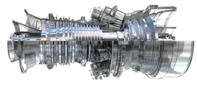
In power systems engineering, "inertia" is a concept that typically refers to rotational inertia or rotational kinetic energy. For synchronous systems that run at some nominal frequency (i.e. 50Hz or 60Hz), inertia is the energy that is stored in the rotating masses of equipment electro-mechanically coupled to the system, e.g. generator rotors, fly wheels, turbine shafts.
Derivation
Below is a basic derivation of power system rotational inertia from first principles, starting from the basics of circle geometry and ending at the definition of moment of inertia (and it's relationship to kinetic energy).
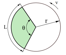
The length of a circle arc is given by:
where Failed to parse (Conversion error. Server ("https://wikimedia.org/api/rest_") reported: "Cannot get mml. Server problem."): {\displaystyle L} is the length of the arc (m)
- is the angle of the arc (radians)
- is the radius of the circle (m)
A cylindrical body rotating about the axis of its centre of mass therefore has a rotational velocity of:
where is the rotational velocity (m/s)
- is the time it takes for the mass to rotate L metres (s)
Alternatively, rotational velocity can be expressed as:
where is the angular velocity (rad/s)
- is the speed in revolutions per minute (rpm)
The kinetic energy of a circular rotating mass can be derived from the classical Newtonian expression for the kinetic energy of rigid bodies:
where is the rotational kinetic energy (Joules or kg.m2/s2 or MW.s, all of which are equivalent)
- is the mass of the rotating body (kg)
Alternatively, rotational kinetic energy can be expressed as:
where is called the moment of inertia (kg.m2).
Notes about the moment of inertia:
- In physics, the moment of inertia is normally denoted as . In electrical engineering, the convention is for the letter "i" to always be reserved for current, and is therefore often replaced by the letter "j", e.g. the complex number operator i in mathematics is j in electrical engineering.
- Moment of inertia is also referred to as or , where . WR2 literally stands for weight x radius squared.
- WR2 is often used with imperial units of lb.ft2 or slug.ft2. Conversions factors:
- 1 lb.ft2 = 0.04214 kg.m2
- 1 slug.ft2 = 1.356 kg.m2
Normalised Inertia Constants
The moment of inertia can be expressed as a normalised quantity called the inertia constant H, calculated as the ratio of the rotational kinetic energy of the machine at nominal speed to its rated power (VA):
where is the inertia constant (s)
- is the nominal mechanical angular frequency (rad/s)
- is the nominal speed of the machine (revolutions per minute)
- is the rated power of the machine (VA)
Generator Inertia
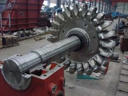
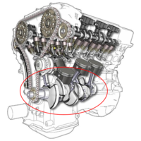
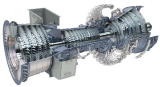
The moment of inertia for a generator is dependent on its mass and apparent radius, which in turn is largely driven by its prime mover type.
Based on actual generator data, the normalised inertia constants for different types and sizes of generators are summarised in the table below:
| Machine type | Number of samples | MVA Rating | Inertia constant H | ||||
|---|---|---|---|---|---|---|---|
| Min | Median | Max | Min | Median | Max | ||
| Steam turbine | 45 | 28.6 | 389 | 904 | 2.1 | 3.2 | 5.7 |
| Gas turbine | 47 | 22.5 | 99.5 | 588 | 1.9 | 5.0 | 8.9 |
| Hydro turbine | 22 | 13.3 | 46.8 | 312.5 | 2.4 | 3.7 | 6.8 |
| Combustion engine | 26 | 0.3 | 1.25 | 2.5 | 0.6 | 0.95 | 1.6 |
Relationship between Inertia and Frequency
Inertia is the stored kinetic energy in the rotating masses coupled to the power system. Whenever there is a mismatch between generation and demand (either a deficit or excess of energy), the difference in energy is made up by the system inertia.
For example, suppose a generator suddenly disconnects from the network. In that instant, the equilibrium in generation and demand is broken and demand exceeds generation. Because energy must be conserved, there must always be energy balance in the system and the instantaneous deficit in energy is supplied by the system inertia. However, the kinetic energy in rotating masses is finite and when energy is used to supply demand, the rotating masses begin to slow down. In aggregate, the speed of rotation of these rotating masses is roughly proportional to the system frequency and so the frequency begins to fall. New generation must be added to the system to reestablish the equilibrium between generation and demand and restore system frequency, i.e. put enough kinetic energy back into the rotating masses such that it rotates at a speed proportional with nominal frequency (50/60 Hz).
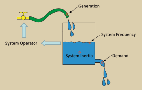
The figure to the right illustrates this concept by way of a tank of water where system demand is a flow of water coming out of the bottom of the tap and generation is a hose that tops up the water in the tank (here the system operator manages the tap, which determines how much water comes out of the hose). The system frequency is the water level and the inertia is the volume of water in the tank. This analogy is instructive because it can be easily visualised that if system inertia was very large, then the volume of water and the tank itself would also be very large. Therefore, a deficit of generation would cause the system frequency to fall, but at a slower rate than if the system inertia was small. Likewise, excess generation would fill up the tank and cause frequency to rise, but at a slower rate if inertia is very large.
Therefore, it can be said that system inertia is related to the rate at which frequency rises or falls in a system whenever there is a mismatch between generation and load. The standard industry term for this is the Rate of Change of Frequency (RoCoF).
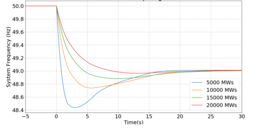
Figure 4 shows the system frequency response to a generator trip at different levels of system inertia. It can be seen that the rate of change of the frequency decline increases as the system inertia is decreased. Furthermore, the minimum frequency that the system falls to (called the frequency nadir) is also lower as system inertia is decreased.
