2 Winding Transformer Models
Positive Sequence Model
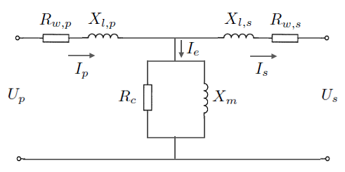
The standard positive sequence model for a two-winding transformer has the following per-unit parameters:
- = primary side terminal voltage (pu)
- = secondary side terminal voltage (pu)
- = primary winding resistance (pu)
- = primary winding leakage reactance (pu)
- = secondary winding resistance (pu)
- = secondary winding leakage reactance (pu)
- = magnetising reactance (pu)
- = eddy current / core losses (pu)
- = primary current (pu)
- = secondary current (pu)
- = magnetising current (pu)
Zero Sequence Models
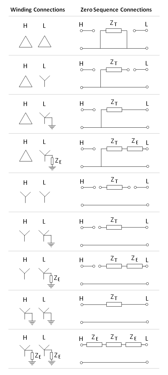
The zero sequence model of a transformer depends on the winding and neutral earthing arrangements. The figure below presents simplified zero sequence models (ignoring the magnetising branch and with all leakage impedances lumped together) for the most common types of two-winding transformer connections. Note that all impedances are in per unit values.
A key insight about transformer zero sequence connections stems from one of the fundamental tenets of transformers: a current will only flow in one winding if there is a corresponding current in the other winding (ignoring magnetising currents).
This is important to understand why zero sequence current can flow in a delta-wye transformer with the star point earthed. Clearly on the wye winding, zero sequence current can flow to earth through the star point, but zero sequence current must also be able to circulate in the delta windings.
This also explains why no zero sequence current can flow in wye-wye transformers (with only one star point earthed). A zero sequence current would need to induce a current in the unearthed wye winding, but there is nowhere for the current to go. Thus it is shown as disconnected in the zero sequence equivalent circuit.
Effects of Core Construction
The simplified zero sequence models in the previous section ignored the magnetising branch. For shell type and 5-limb core type transformers, this is a reasonable assumption since the zero sequence magnetising reactance is large and similar to that of the positive (and negative) sequence magnetising reactance.
However, care must be taken for the zero-sequence modelling of 3-limb core type transformers. The shape of the core is such that during unbalanced operation (i.e. presence of zero-sequence currents), the flux is forced to take a path outside of the transformer core (low reluctance) and through the air, tank, oil and transformer frame (high reluctance). As magnetising reactance is inversely proportional to reluctance, the high reluctance path causes the magnetising reactance in 3-limb core type transformers to be significantly lower than in 5-limb core type or shell type transformers.
This is particularly relevant for wye connected windings, especially Yyn (or YNy) connections with only one star point earthed. We mentioned previously that zero sequence currents cannot flow in this configuration. But for 3-limb core type transformers, the alternative flux path through the tank, oil and frame allows for sufficient zero-sequence current to be induced and circulate around the tank and frame. In this way, the tank and frame acts like an internal delta winding.
References
- [1] Blackburn, J., "Symmetrical Components for Power Systems Engineering", CRC Press, 1993
- [2] Tleis, N., "Power Systems Modelling and Fault Analysis - Theory and Practice", Newnes, 2008


